Movincool CMW30 Bedienungsanleitung

Stöbern Sie online oder laden Sie Bedienungsanleitung nach Spülung Movincool CMW30 herunter. MovinCool CMW30 User Manual Benutzerhandbuch

  • Herunterladen
  • Zu meinen Handbüchern hinzufügen
  • Drucken
  • Seite
    / 2
  • Inhaltsverzeichnis
  • LESEZEICHEN
  • Bewertet. / 5. Basierend auf Kundenbewertungen
Seitenansicht 0
1. Inventory
After unpacking, please check to make sure you have the following items. If any of these items
were not included in the box or appear damaged, please contact your MovinCool reseller for
replacement (see Fig.1).
1
INSTALLATION MANUAL
For CMW30
Compressor Assembly (Part No. 484650-3150)
Compressor ( 1 )
Pipe 1 (1) Pipe 2 (1)
Water
Supply
Water
Return
Drain Plug
Drain Port
Shut-off Valve
CMW30
Unit
Fig. 3
Fig. 2
Fig. 1
Insulator B (1)Insulator A (1)
Cushion (3)
2-2. Loosen one (1) bottom screw, then remove nine (9) screws to take off the service panel
(see Fig. 3 ).
Screws (9)
Bottom Screw (1)
Service Panel
2. Removal of Compressor Assembly
WARNING: Disconnect power supply from the CMW30 unit before performing any
service. Beware that some residual voltages may remain in the unit
immediately after the power is disconnected.
!
2-1. Shut off the water supply and return, then remove the drain plugs to drain the water from
the condenser via the drain ports (see Fig. 2).
4
P/N 484007-3511 Second Issue: September 2011
2- 8. Braze at point A and B, then remove pipe 1. Braze at point C and D, then remove pipe 2.
Remove three (3) nuts and three (3) washers and keep them for installation, then remove the
compressor. Remove three (3) cushions and discard (see Fig. 9).
MC-W Wire
MC-V Wire
MC-U Wire
OLC-1 Wire
OLC-2 Wire
Nut (3)
Washer (3)
Cusion (3)
Fig. 9
Pipe 2
D
C
Pipe 1
A
B
Accumulator
Compressor
3. Installation of Compressor Assembly
3- 1. Install three (3) cushions to the bolts and mount the supplied compressor to the unit. Insert three (3)
washers and tighten three (3) nuts at the torque of 8.3 ± 2.1 ft.lbf (11.3 ± 2.9 N.m). (see Fig. 9).
3- 2. Braze pipe 1 at point A and B, then braze pipe 2 at point C and D (see Fig. 9).
3- 3. Re-install overload relay, wires, and plastic cover after brazing (see Fig. 10).
3- 4. Apply insulator A to the accumulator, then vacuum and charge the R-410A refrigerant with the
amount of 2.31 lb (1.05Kg) through tube 1, and then apply the insulator B to tube 1 (see Fig. 8).
3- 5.
3- 6. Install the rear panel, AC Fan motor, top panel, service panel, reconne
ct the inlet and outlet water
pipes, install drain plugs, and turn on the water supply in the reverse order of the removal steps.
Reconnect CN103, CN104, CN105, and CN7 wires to the relay board (see Fig.4).
CAUTION: To avoid damage, remove the plastic cover, wires, and overload relay
from compressor before brazing at point D (see Fig. 10).
Fig. 10
Plastic Cover
Overload Relay
!
Seitenansicht 0
1 2

Inhaltsverzeichnis

Seite 1 - INSTALLATION MANUAL

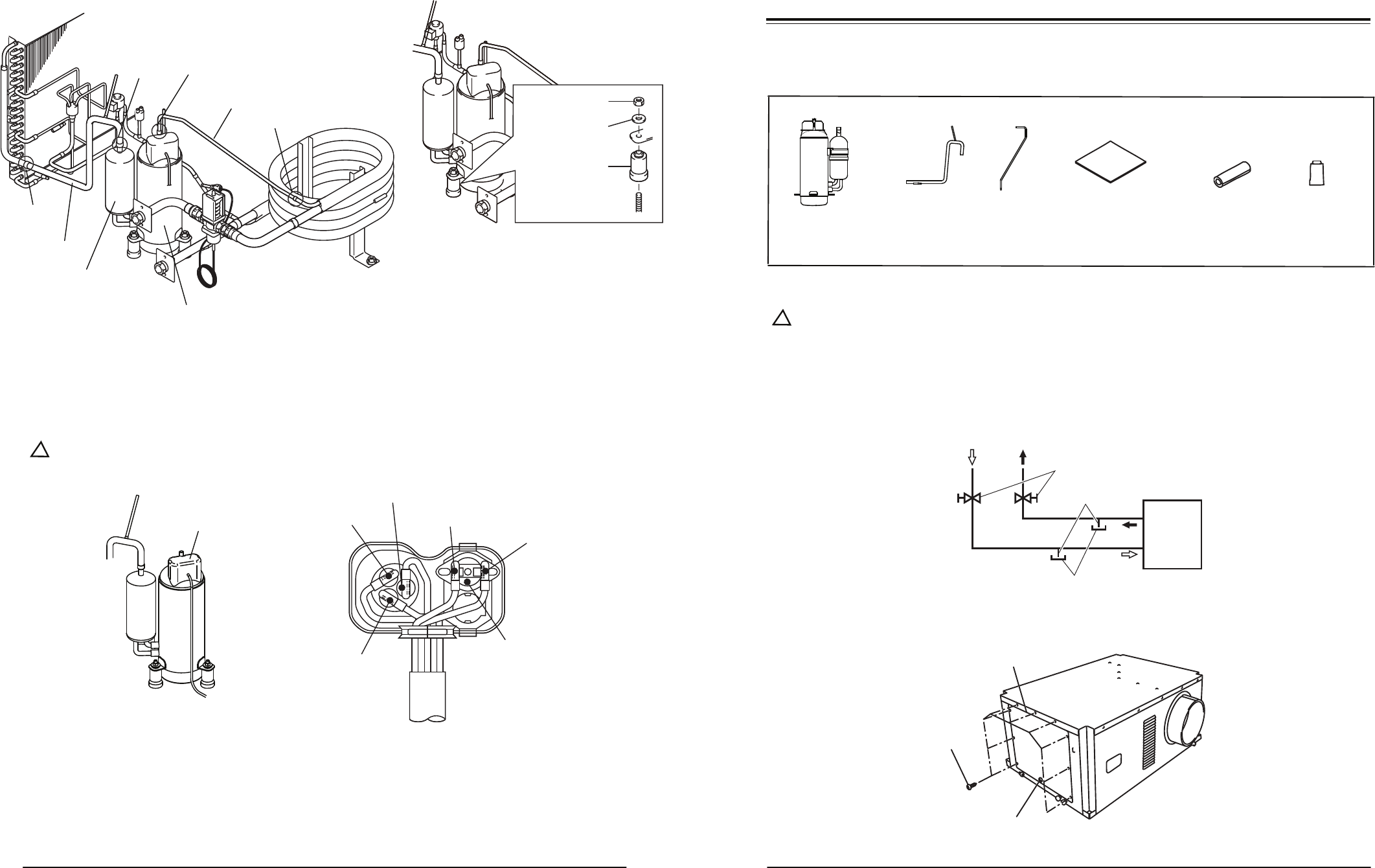
1. InventoryAfter unpacking, please check to make sure you have the following items. If any of these items were not included in the box or appear dama

Seite 2 - Relay Board

32- 6. Remove four (4) screws and loosen two (2) bottom screws. Remove eleven (11) screws, and then remove the rear panel (see Fig. 7).Screws

Kommentare zu diesen Handbüchern

Keine Kommentare